[Previous Chapter] [Next Chapter]
 [
Table of Contents] [Home] [Glossary] [Video] [Help]

Chapter 3
KINEMATICS:
COORDINATE SYSTEMS FOR DESCRIBING EYE POSITION

Key Words: degrees of freedom, references, tangent screen projection geometry, Cartesian coordinate systems, polar system, Donder's law, Listing's Law, false torsion, iso-vergence surface

Outline
III. Kinematics- Description and Quantification of eye position and orientation

  • Coordinate system geometry
    Reference -pivot point- center of rotation & centrode
    Reference direction- primary direction of gaze
    Three degrees of freedom for orientation.
    Rotational vectors (show primary, secondary, and tertiary positions)
    Tangent screen projection geometry- useful for clinical description
    Four Cartesian coordinate systems- (Fick, Helmholtz, Harmes, Hess)
    One Polar coordinate system (Listing- ball membrane model)
     
  • Torsion Laws & false torsion
    Donders- constant torsion in all positions independent of path of eye
    Listing- zero torsion in Listing's coordinate system Ball-membrane model
    False torsion of Cartesian systems- Maddox rod laser demo
     
  • Isovergence surface


Coordinate system geometry

Reference directions
Ocular kinematics is the description of position and orientation in space that requires six degrees of freedom (df): three for position and three for orientation.  Since the eye does not translate significantly, we need to quantify only the orientation.  (Generally, we use the term position, such as "The eye is positioned to look at the target."  However, this term is technically incorrect since we are actually describing the eye's orientation.)  We need an axis of rotation for each of the three degrees of freedom defining orientation.  We also need a pivot point reference (the center of rotation) and a starting direction (primary position or direction of gaze).  Primary positions of the two eyes are parallel and they are orthogonal to the facial or equatorial plane.  Description of eye movements is simply a description of a rotating sphere (spherical geometry).  The eye rotates in a virtual socket made of the orbit and eye muscle basket.  The sphere rotates around a point located 13mm posterior to the cornea called the center of rotation.  Actually the eye doesn't rotate about a fixed point but rather a fixed arc called the centrode.  Because the center of rotation is not the center of the eye's entrance pupil or nodal point, whenever the eye rotates it causes a small translation of the retinal image.

Picture

Fig 3.1  Body and space centrodes of the human eye. Note that the eye does not rotate about a single fixed point.

Clinically we have to describe the position of the eyes for a variety of reasons.  We want to quantify eye turns, magnitude of abnormal nystagmus, monocular aiming errors of the eyes and phorias.  This is all fairly easy if we describe pure vertical and horizontal movements but it becomes difficult if we have oblique movements.  This is because there are several different ways that we could describe how the eye reached an oblique (tertiary) point starting from the primary position of gaze, e.g. we could describe eye position with a combination of vertical and horizontal rotation components or a single rotation about an oblique axis that was perpendicular to the plane containing the primary and tertiary eye position.  Each of these approaches would result in a different torsion angle of the eye in the tertiary direction of gaze.  Physiologically, the eye doesn't follow any of these coordinate systems.  We only use these systems for our convenience to describe eye position with as few degrees of freedom as possible.

Kinematics:
Kinematics is the study of motion, exclusive of the influences of mass and force.  In optometry it is used to describe eye position relative to the primary position of gaze and the position of targets in the visual field with respect to the visual axis.  These measures are important in quantifying eye misalignment disorders such as strabismus and also for specifying the location of blind areas in the visual field.  Optometry uses five different coordinate systems that are based upon specific instruments used to quantify eye position and retinal location.  The eye position will be quantified differently by each coordinate system, however the values of one coordinate system can be transposed into another system.  To obtain valid measures of eye position, it is important to use the coordinate system for which a measurement instrument is designed.

Euclidian and Spherical Geometry:
How do we specify eye position?  When we change our gaze from one target to another we say the eye has moved to a new position.  But in fact it has not changed its position in space (this would be a translation) but rather it has rotated about a small pivot point within the eye so that the visual axis points in a new direction.

We do not usually describe rotation of the eye in terms of spherical geometry or rotations about axes.  Instead we describe eye direction in terms of where the visual axis would intersect a tangent screen (Euclidean geometry).  We use prism diopters rather than degrees of rotation to quantify eye position and retinal image location because the prism diopter is based upon a tangent measure i.e., a displacement from the center point on a tangent screen divided by the viewing distance.


Fig 3.2  Horizontal rotation about a vertical axis, illustrating the path the eye follows.  Note that for a vertical axis that moves with the eye (ìeye-fixed axisî), a straight path results.  Whereas a vertical axis that is stationary in the head results in a curved path.

Clinically Applied Coordinate Systems:
Much of the effort in teaching is to describe spherical coordinate systems and how to transform spherical rotation onto the Euclidean space of the tangent or projection screen.  For this purpose a gimbaled laser projector can be used to illustrate three classic coordinate systems introduced early by Fick, Helmholtz and Listing.  The laser is mounted on the back of a large-scale Plexiglas sphere that simulates rotation of the eye about various axes that pass through its center of rotation. The laser projects from the sphere onto a flat front projection screen to illustrate the path the eye would follow on the tangent screen during pure horizontal rotation about a vertical axis and pure vertical rotation about a horizontal axis.  These paths are either straight or curved depending on whether the coordinate system uses axes that move with the eye or remain stationary in the head.  (See Fig 3.2)  The figures below illustrate a projection of a vertical cross onto a sphere about the eye (Left) and the projection of that cross onto a Tangent plane (Right) for five different coordinate systems.


Fig 3-3  Fick Coordinate System. (Head-fixed vertical axis/ Eye-fixed horizontal axis)  Used with table-mounted projectors (e.g.,major amblyoscope).


Fig 3-4  Helmholtz Coordinate System. (Eye-fixed vertical axis/ Head-fixed horizontal axis)  Used with wall-mounted projectors.


Fig 3-5  Harms Coordinate System. (Vertical and horizontal axes both eye-fixed)  Used with hand-held Lancaster projectors.


Fig 3-6  Hess Coordinate System. (Vertical and horizontal axes both head-fixed)  Used with hand-held prisms.


Fig 3-7  Listing Coordinate System.  (Based on polar geometry.)  Used with perimeter.

The horizontal path the eye takes while fixed in different amounts of elevation (isoelevation curves) and the vertical path the eye takes while fixed in different amounts of azimuth (isoazimuth curves) result in the classic clinical projection screens shown above.  These screens are used to map the characteristics of ocular misalignment that vary with direction of gaze in cases of non-comitant strabismus.  The five examples shown above (Fick, Helmholtz, Harms, Hess and Listing) are used when eye position is measured respectively with a major amblyoscope, a wall mounted projector, hand held Lancaster projectors, hand held prisms, and a perimeter.

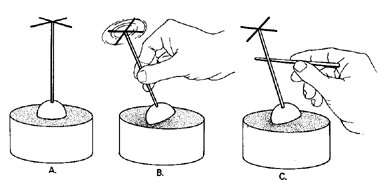
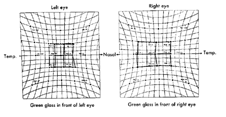
Ocular torsion about the visual axis is demonstrated by projecting the laser through a combination of vertical and horizontal Maddox cylinders mounted on the front of the sphere which produce an image of a cross on the projection screen.  As the projector aims in different directions the projected image of the cross becomes distorted or scissored and torted (false torsion).  The orientation of the projected cross can be used to illustrate the different amounts of torsion about the visual axis that result when various coordinate systems are used to point the eye into tertiary directions of gaze.  The cross in the figures above show the actual torsion of the eye as descirbed by Listing.  The orientation of the vertical and horizontal arms of the cross for the 4 Cartesian systems would follow the isoelevation and isoazimuth lines of the figure.  The difference between the orientation of the Listing's cross and the grid represents false torsion.

The direction of the visual axis can be described in spherical geometry as rotations about one or more axes.  Optometry utilizes 5 different coordinate systems to describe direction of gaze and each coordinate system is made up of a unique set of axes to describe rotation.  Normally we would need 6 degrees of freedom to describe the direction of gaze in 3-D space.  Three degrees of freedom describe translation and three describe rotation.  Because we keep the head stationary and the eye primarily rotates in the orbit, we only need the three rotational degrees of freedom.  These are expressed as 3 axes of rotation that pass through the center of rotation and they rotate the eye horizontally, vertically and torsionally.  Direction of gaze can be described by the amount of rotation about each of these axes.


Fig 3.8  Rotational axes of the eye used to describe direction of gaze for Cartesian coordinate systems.

The coordinate systems described above are man made, i.e. they are for our convenience because they provide a way for us to quantify an eye position.  They don't necessarily describe the actual movements of the eye needed to change direction of gaze, however one of the coordinate systems (Listings) has been used for this purpose.  The various coordinate systems differ from one another in terms of whether the axes of rotation stay stationary with respect to the head or whether they move with the eye.  Four of the systems are based upon Cartesian geometry and the fifth is based upon polar geometry.  All of them have specific clinical applications for describing how projectors move targets in space to quantify eye position or visual fields.

Head and Eye reference Axes of Rotation in Cartesian Coordinate Systems:
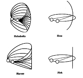
Two of the Cartesian coordinate systems have a combination of head-fixed and eye-fixed axes which are nested or gimbaled.  A tripod is an example of such system that was devised by Fick.  In the Fick system the vertical axis about which horizontal rotations are made remains earth fixed whereas the horizontal axis about which vertical rotations are made moves with the instrument mounted on the tripod. 

Picture

Fig 3.9  Example of a tripod based on the Fick Coordinate System.

The head itself is another example of a Fick coordinate system where the neck (vertical axis) remains fixed with respect to the body as the head elevates but the interaural axis (horizontal axis) moves as the head rotates about its vertical axis.  This Fick coordinate system is use clinically to describe the positions of the two eyes measured with table mounted projectors such as the major amblyoscope.  A similar system devised by Helmholtz uses a system of axes that are rotated 90 degrees relative to the Fick system.  The Helmholtz system uses a head- or earth-referenced horizontal axis and eye- or projector-referenced vertical axis and it is used clinically to describe eye position with wall mounted projectors.

Two other Cartesian coordinate systems are not nested.  In the Hess system both the horizontal and vertical axes are earth referenced.  Clinically this system is used to quantify direction of gaze measured with hand held prisms that are oriented with optical bases along earth-referenced vertical and horizontal axes.  Finally the Harms system utilizes eye or projector referenced vertical and horizontal axes. Clinically this system is used to describe the direction of lights projected from hand held flashlights onto a Lancaster projection screen.  Hand held flashlights move in a Harms system because vertical movements of the arm about the shoulder and elbow affect the orientation of the vertical axis of rotation (the upper arm) and horizontal movements of the arm about the shoulder affect the orientation of the horizontal axis of rotation (the elbow).

Fig 3.10  Primary axes of Fick.

Fig 3.11  Listingís Plane

Listing's Plane
A fifth system developed by Listing, which is based upon polar geometry, approximates the physiological coordinate system used by the oculomotor system.  Listing reduced the number of degrees of freedom to describe direction of gaze from 3 to 2.  Rotation of the eye to any direction of gaze could be described as though it resulted from a rotation about a single axis within the equatorial plane (Listing's plane - See Fig 3-11).  Unlike the Cartesian systems described above, Listing's system did not require a third degree of freedom (eye torsion about the line of sight) to describe the orientation of the eye around the visual axis because in Listing's system, the torsion of the eye is independent of the path the eye followed to reach any given direction of gaze (Donder's Law).  Clinically this system is used in perimetry to describe the location of blind areas in the visual field.

Picture

Fig 3.12  The figure above illustrates Listing coordinate system for movements of the eye restricted by an elastic membrane.  Muscular ligaments that attach the eye to the orbit wall produce this membrane-like effect.

Tangent Screen Projections:
As described above each of these spherical coordinate systems will project differently onto a tangent screen.  If you are measuring eye position from the location of images projected by the subject onto a tangent screen its important to use screen coordinates that correspond to the rotational coordinate system of the projectors or image displacement system.  The most common way of measuring eye position is by prism neutralization during the alternate cover test in primary and tertiary directions of gaze.

Picture

Fig 3.13  Example of Hess chart used clinically to describe horizontal and vertical deviation measured with prisms.

The amount of horizontal and vertical deviation measured with prisms is described by the Hess chart (shown above).  If hand held flashlights are used in the Lancaster test then a Harms chart is used.  The Lancaster test will require more vertical and horizontal displacement to quantify a tertiary direction of the eye than when prisms are used because the Hess screen is hyperbolic and the Harms screen is rectilinear. 

Torsion Laws & False Torsion
Each coordinate system needs three degrees of freedom to describe eye position, where the third degree is eye torsion about the line of sight.  The first two degrees of freedom in the Cartesian systems are vertical and horizontal rotation.   If we don't make any torsion adjustment, the four Cartesian systems will come up with a different amount of torsion to describe teritary eye position.   The vertical axis projected by the laser up and to the left remains vertical in the Fick system, but it is levotorted in the Helmholtz system.  Thus if we put a vertical afterimage on your fovea, its perceived orientation at any location on the tangent screen would be the same as the orientation of the vertical chart grid lines we just described.

All four of the spherical cartesian coordinate systems described earlier result in different torsion values than those predicted by Listing's coordinate system.  Therefore, an additional torsional adjustment is needed after making the vertical and horizontal rotations in order to have the same zero torsion as predicted by Listing's law.  Because the eye obeys Listing's law and really doesn't need to make this additional adjustment, we call this torsion needed with man-made coordinate systems false torsion.  Values of the false torsion needed for the Helmholtz system to conform to Listing's law and the real torsional posture of natural eye movements are given in Helmholtz's book on page 62.  Another interpretation of false torsion is suggested by your text book Adler's Physiology of the Eye on page 108.  This interpretation states that false torsion is any twisting or tilt of the vertical afterimage on the tangent screen away from true gravity referenced vertical.  Under this system, the only coordinate systems that don't have false torsion are Fick and Harms.

Isovergence
How do we describe pure versional or conjugate movements without any vergence component?  This type of movement is described by an isovergence curve.  We want a surface that subtends a constant angle at the eyes everywhere in space.  This is a circle passing through the fixation point in primary gaze and the centers of rotation of the two eyes.


Fig 3.14  Iso-vergence circles in the visual plane.  Points A and B have the same Vergence angle, as do points C and D.

Note that points A and C have the same Version angle.  So do points B and D.


Theorum: any two points on a circle subtend a constant angle with any other point on the same circle. Figure 3.15 (right) illustrates isovergence circles for convergence ranging from 20-60 degrees.  The oblique lines represent iso-version lines where direction of gaze is constant and vergence varies.  The isovergence circle is correct for all coordinate systems that describe horizontal eye movements in the visual plane.  However if you try to describe vertical or oblique conjugate movements you do have to take into consideration the coordinate systems as illustrated in Figure 3.16. (below)

Picture

Review Questions:

  1. How many degrees of freedom are needed to describe eye orientation?
  2. What are the head and eye referenced axes for the Fick and Helmholtz coordinate systems?
  3. Define Listing's Law.
  4. Define Donder's Law.

[Previous Chapter] [Next Chapter]
 [Table of Contents] [Home] [Glossary] [Video] [Help]